


PermalinkIntroduction
Air pollution is a growing concern worldwide, with significant impacts on human health and the environment. Monitoring air quality in real-time is essential for understanding pollution levels and taking necessary precautions.
Air pollution is a growing global concern, with harmful pollutants affecting both human health and the environment. According to the World Health Organization (WHO), exposure to poor air quality can lead to respiratory diseases, cardiovascular problems, and even reduced life expectancy. While governments and agencies operate large-scale air quality monitoring stations, personal and localized monitoring is equally essential — especially in enclosed spaces such as homes, offices, and factories.
This blog will guide you through building an Air Quality Monitoring System using the Wio Terminal, DHT22 sensor, and Grove Multichannel Gas Sensor. The system provides real-time measurements of temperature, humidity, and air pollutants such as CO (Carbon Monoxide), NO₂ (Nitrogen Dioxide), NH₃ (Ammonia), and VOCs (Volatile Organic Compounds).
PermalinkWhy Air Quality?
Air quality monitoring has become crucial due to the increasing levels of pollutants indoors and outdoors. Here are some reasons why monitoring air quality is important:
Health Protection: Detect harmful gases that may lead to respiratory issues, headaches, dizziness, or long-term health problems.
Early Warning System: Identify pollutant spikes in industrial areas, near roadways, or even in homes due to cooking gases and chemicals.
Data for Smart Environments: Contribute to smart home automation by activating air purifiers or ventilation systems when pollutant levels rise.
Climate Awareness: Monitor trends in air quality to make informed decisions on outdoor activities or environmental protection measures.
With this DIY air quality monitor, you can take control of the air you breathe and stay informed about your environment in real-time.
PermalinkComponents Required
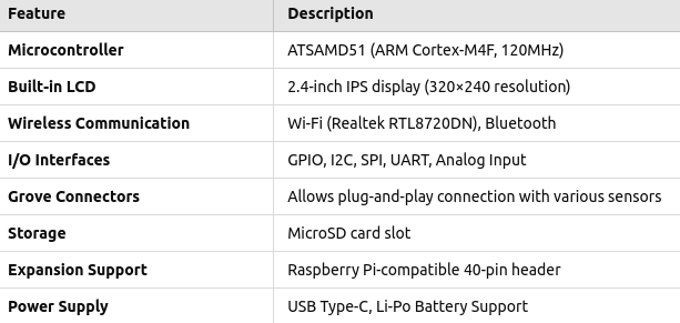
Wio Terminal
Grove multichannel gas sensor v2
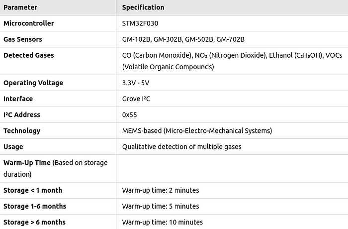
Technical Specifications - Grove multichannel gas sensor v2
3. Grove DHT22 Temperature and Humidity sensor.
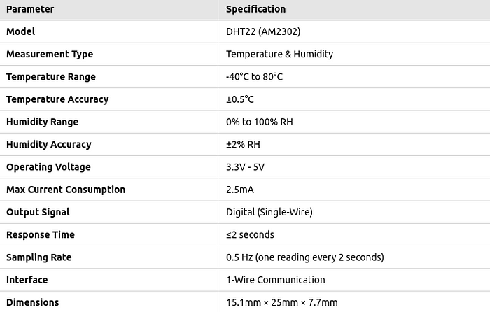
Technical Specification - DHT22 Sensor
PermalinkProject Flow
Connect the DHT22 and the multichannel sensor to the Wio Terminal
Write Code for Reading the data from the sensor
Draw UI Design
Convert UI Design to Code
Display Sensor data on Display with UI Design
PermalinkWhy Wio Terminal ?
The Wio Terminal is an all-in-one embedded development board designed by Seeed Studio. It is powered by the ATSAMD51 microcontroller (based on the Cortex-M4F core) and comes with built-in Wi-Fi, Bluetooth, an LCD display, and multiple I/O interfaces.
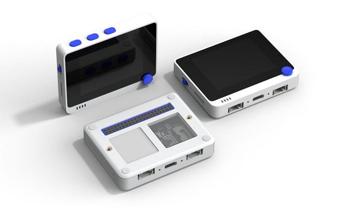
Unlike traditional microcontroller boards (such as Arduino Uno), the Wio Terminal integrates sensor connectivity, display output, and wireless communication into a compact device, making it ideal for IoT, AI, and embedded applications
For more details about Wio Terminal and its various use cases , please refer this link https://wiki.seeedstudio.com/Wio-Terminal-Getting-Started/
PermalinkCircuit Diagram
PermalinkProcedure for setting up the wio terminal with Arduino IDE.
To develop an Air Quality Monitoring System using the Wio Terminal, we first need to set up the Arduino IDE and install the necessary libraries for the sensors.
PermalinkStep 1: Install Arduino IDE
Download and install the latest version of Arduino IDE from Arduino’s official website. https://www.arduino.cc/en/software
PermalinkStep 2: Install Wio Terminal Board Support
https://wiki.seeedstudio.com/Wio-Terminal-Getting-Started/ this link has the instruction for Wio Terminal Setup in Arduino IDE.
PermalinkStep 3: Install Required Libraries
Navigate to Sketch → Include Library → Manage Libraries and install the following:
DHT sensor library (https://github.com/Seeed-Studio/Grove_Temperature_And_Humidity_Sensor) – For temperature & humidity readings.
TFT_eSPI — For Wio Terminal’s built-in LCD display.
Grove Multichannel Gas Sensor Library (https://github.com/Seeed-Studio/Seeed_Multichannel_Gas_Sensor/) — For detecting CO, NH3, NO2, and VOCs.
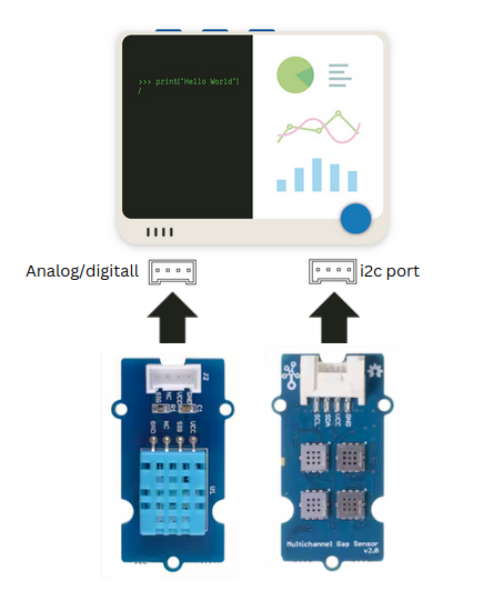
PermalinkStep 4: Wiring the Sensors to Wio Terminal
The DHT22 sensor requires only a single Grove A0 port.
The Multichannel Gas Sensor communicates via I2C, so it should be connected to the I2C Grove port on the Wio Terminal.
Power the Wio Terminal via a USB Type-C cable.
Grove Multichannel Gas Sensor
Grove DHT22 Sensor
PermalinkStep 5: Design the UI for the Wio Terminal Display
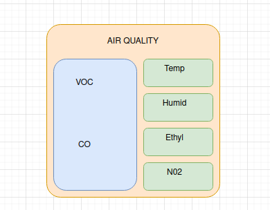
A simple UI design can be created using draw.io website. Later the code is written based on this design using the tft library.
PermalinkStep 6: Uploading the Code
Once everything is set up, upload the following code to test the sensors and display data on the Wio Terminal screen.
 #include <TFT_eSPI.h>
  #include <Multichannel_Gas_GMXXX.h>
  #include <Wire.h>
  #include "Grove_Temperature_And_Humidity_Sensor.h"


  #define LIGHTGREEN tft.color565(144, 238, 144)
  #define DARKBLUE tft.color565(0, 0, 139)
  #define GREY tft.color565(128,128,128)


  // Initialize Display
  TFT_eSPI tft = TFT_eSPI();

  // Initialize Gas Sensor
  GAS_GMXXX<TwoWire> gas;

  // Define DHT Sensor
  #define DHTTYPE DHT22
  #define DHTPIN 0
  DHT dht(DHTPIN, DHTTYPE);

  void setup() {
      Serial.begin(115200);
      Wire.begin();

      // Initialize Sensors
      dht.begin();
      gas.begin(Wire, 0x08);

      Serial.println("Sensors Initialized Successfully");

      // Initialize Display
      tft.init();
      tft.setRotation(3);
      tft.fillScreen(GREY);
  }

  void loop() {
      float temp_hum_val[2] = {0};

      // Read Temperature & Humidity
      int temperature = 0, humidity = 0;
      if (!dht.readTempAndHumidity(temp_hum_val)) {
          humidity = (int)temp_hum_val[0];
          temperature =(int) temp_hum_val[1];
      } else {
          Serial.println("Failed to read temperature & humidity!");
      }

      // Read Gas Sensor Data
      int NO2_val = gas.getGM102B();
      int Ethanol_val = gas.getGM302B();
      int VOC_val = gas.getGM502B();
      int CO_val = gas.getGM702B();

      // Update Serial Monitor
      Serial.print("Humidity: "); Serial.print(humidity);
      Serial.print(" | Temperature: "); Serial.print(temperature);
      Serial.print(" | NO2: "); Serial.print(NO2_val);
      Serial.print(" | Ethanol: "); Serial.print(Ethanol_val);
      Serial.print(" | VOC: "); Serial.print(VOC_val);
      Serial.print(" | CO: "); Serial.println(CO_val);

      // UI Colors
      uint16_t bgColor = TFT_WHITE;
      uint16_t boxColor = DARKBLUE;
      uint16_t textColor = TFT_WHITE;
      uint16_t highlightColor = TFT_YELLOW;

      // Air Quality Box (Left)
      int aqBoxX = 10, aqBoxY = 45, aqBoxWidth = 110, aqBoxHeight = 190;
      tft.fillRoundRect(aqBoxX, aqBoxY, aqBoxWidth, aqBoxHeight, 5, boxColor);
      tft.drawRoundRect(aqBoxX, aqBoxY, aqBoxWidth, aqBoxHeight, 5, TFT_WHITE);

      // Sensor Boxes (Right)
      int boxX = 125, boxWidth = 130, boxHeight = 43;
      int startY = 45, spacing = 50;
      for (int i = 0; i < 4; i++) {
        int boxY = startY + (i*spacing);
        tft.fillRoundRect(boxX, boxY , boxWidth, boxHeight, 5, boxColor);
        tft.drawRoundRect(boxX, boxY , boxWidth, boxHeight, 5, TFT_BLACK);
      }

      // Labels
      tft.setTextColor(textColor, bgColor);
      tft.setTextSize(2);
      // Air Qualoity heding
      tft.setCursor(70,14);
      tft.setTextColor(TFT_GREEN);
      tft.print("AIR QUALITY");

      // Air Quality Box Text
      // Dynamically Position Text Inside Boxes
      tft.setCursor(aqBoxX + 15, aqBoxY + 12);  tft.setTextColor(highlightColor);  tft.print("VOC:");

      tft.setCursor(aqBoxX + 35, aqBoxY + 50);  tft.print(VOC_val);

      tft.setCursor(aqBoxX + 15, aqBoxY + 110);  tft.setTextColor(LIGHTGREEN);  tft.print("CO:");
      tft.setCursor(aqBoxX + 35, aqBoxY + 150);  tft.println(CO_val);

      // Dynamically Set Sensor Values (Right)
      tft.setTextColor(TFT_WHITE);
      tft.setCursor(boxX + 10, startY + 12);  tft.print("Temp: ");   tft.print(temperature);
      tft.setCursor(boxX + 10, startY + spacing + 12);  tft.print("NO2: ");    tft.print(NO2_val);
      tft.setCursor(boxX + 10, startY + 2 * spacing + 12);  tft.print("Humid: ");  tft.print(humidity);
      tft.setCursor(boxX + 10, startY + 3 * spacing + 12);  tft.print("Ethyl: ");  tft.print(Ethanol_val);

      // Update every 2 seconds
      delay(2000);
  }
PermalinkStep 7: Running the Air Quality Monitor
Connect the Wio Terminal to your computer via USB Type-C.
In Arduino IDE, go to Tools → Port and select the correct port for the Wio Terminal.
Click the Upload button (→) in Arduino IDE.
Once uploaded, open the Serial Monitor (
115200 baud rate) to see real-time sensor data.The LCD screen of Wio Terminal will now display temperature, humidity, and gas levels.
PermalinkFinal Result
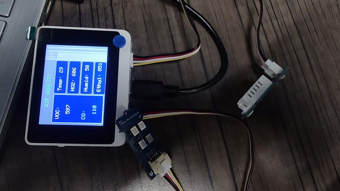
Final output (Excuse me for the Screen Damage :p)

Serial monitor Reading on Arduino (Baud Rate : 115200)
The final Result can be displayed in the Wio Terminal. As for now we’ve only done the monitoring part, In future we will be looking to use IoT connectivity and Dashboard analytics using cloud. Till then keep learning!